NOVEMBER 2017
A Lunar Imaging example using Deconvolution Sharpening and Microsoft ICE
An article in the author’s Astronomy Digest – https://www.ianmorison.com
This was an exercise to image the 6 day old Moon. One problem in imaging the early phases of the Moon is that, by that time that the sky is dark, it will be fairly low above the horizon so the atmosphere will reduce the image quality that one might achieve if it were higher in the sky. As I have described elsewhere in this digest, a way out of this problem is to image the Moon in the infrared as the blue skylight is very largely eliminated so that the contrast in the image will be far better than if imaged in white light. This thus allows the Moon to be imaged when at a higher elevation so helping to ameliorate the effects of atmospheric turbulence. A further advantage is that the near infrared part of the spectrum is less affected by the ‘seeing’ than shorter wavelengths.
To this end, the 6 day old Moon was imaged in the late afternoon of November 24th whilst at an elevation of 19 degrees. The telescope used was a Takahashi FS102 Fluorite refractor mounted on an iOptron MiniTower alt/az mount. The camera employed with it was a Point Grey Chamelion USB2 monochrome camera with a Sony ICX445 1/3” sensor employing 1296 x 964, 3.75 micron, pixels having a peak sensitivity of 64%. Happily, it still has quite reasonable sensitivity in the near infrared. To isolate this part of the spectrum, a 1.25 inch Astronomik Planet IR Pro 742 filter was screwed into the front of the barrel adapter.
Though this is an older Point Grey camera using a USB2 interface and has a maximum frame rate of 18 frames per second I still found that, due to its ~1.2 million pixels, the data rate was greater than my i5 laptop could handle efficiently. It was able to buffer the data in RAM in real time with no frames lost, but could not write this data to either its hard drive or an external mechanical USB3 drive at a sufficient rate to keep up with the data rate and so was taking twice as long to save the data as it took to capture it. This problem was solved by replacing the laptop’s hard drive with an SSD drive and by purchasing an external USB3 SSD drive.
As the lunar imaging was carried out away from mains power points, the laptop was powered through a 1,500 Watt inverter (having a 12 volt input) coupled to a car jump-start battery. (See article on ‘Practical Aspects of Observing and Astroimaging’.)
One advantage of using a larger sensor size webcam is that fewer ‘panes’ are required to cover the surface whilst allowing plenty of overlap for the image compositing program to use in aligning the panes. Only four panes were required for this phase of the Moon. Video sequences of ~600 frames were taken and imported into Registax 6.
Aligning and stacking the video files in Registax 6
I am going to describe the processing of one of the central panes as it contains three close-by interesting craters, Theophilus, Cyrillus and Catharina in ascending order. (The videos are both vertically and horizontally inverted.)
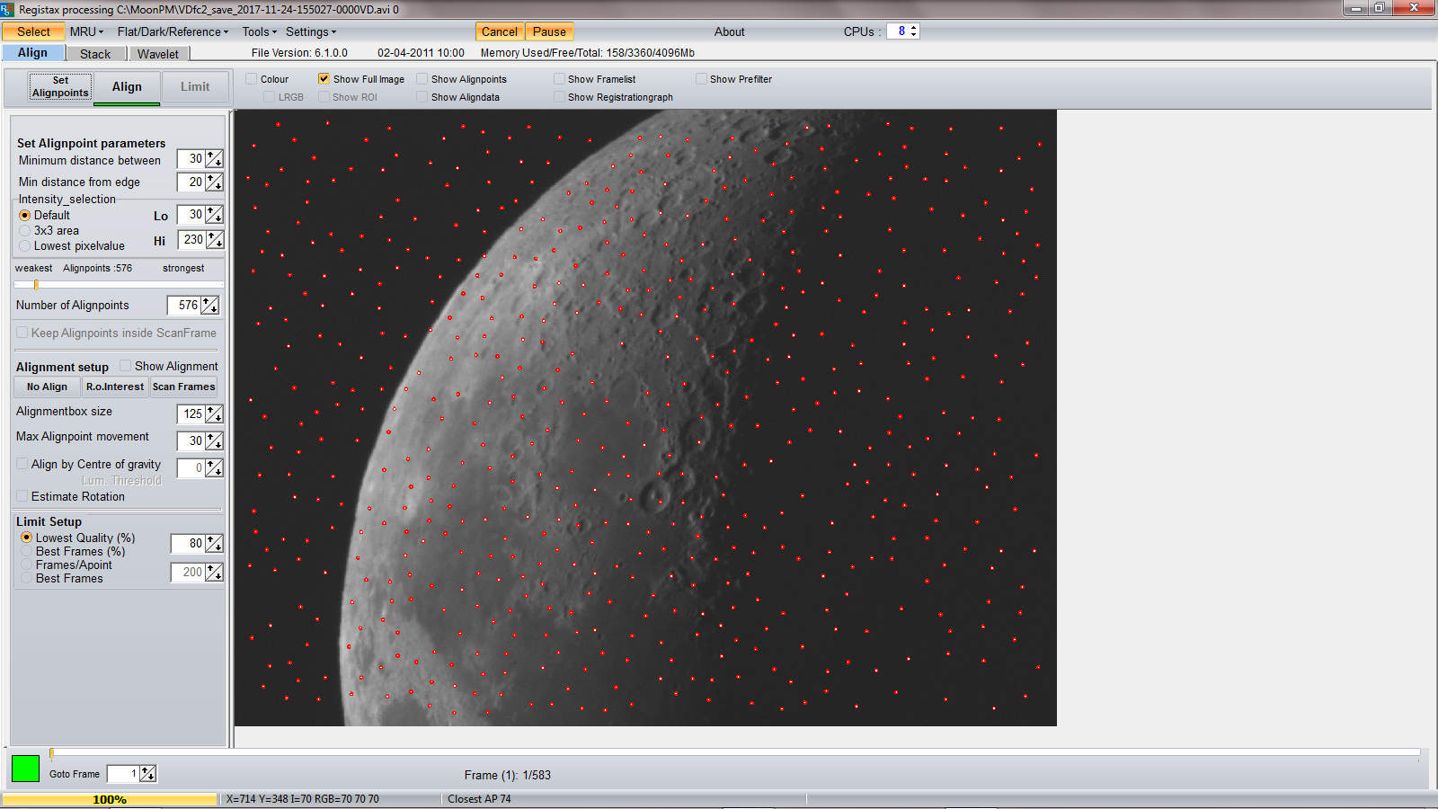
The video sequence was imported into Registax and the ‘Set Align Points’ tab clicked upon. In my view, as is often the case, it then produced far too many align points – some even beyond the lunar surface − as seen below.
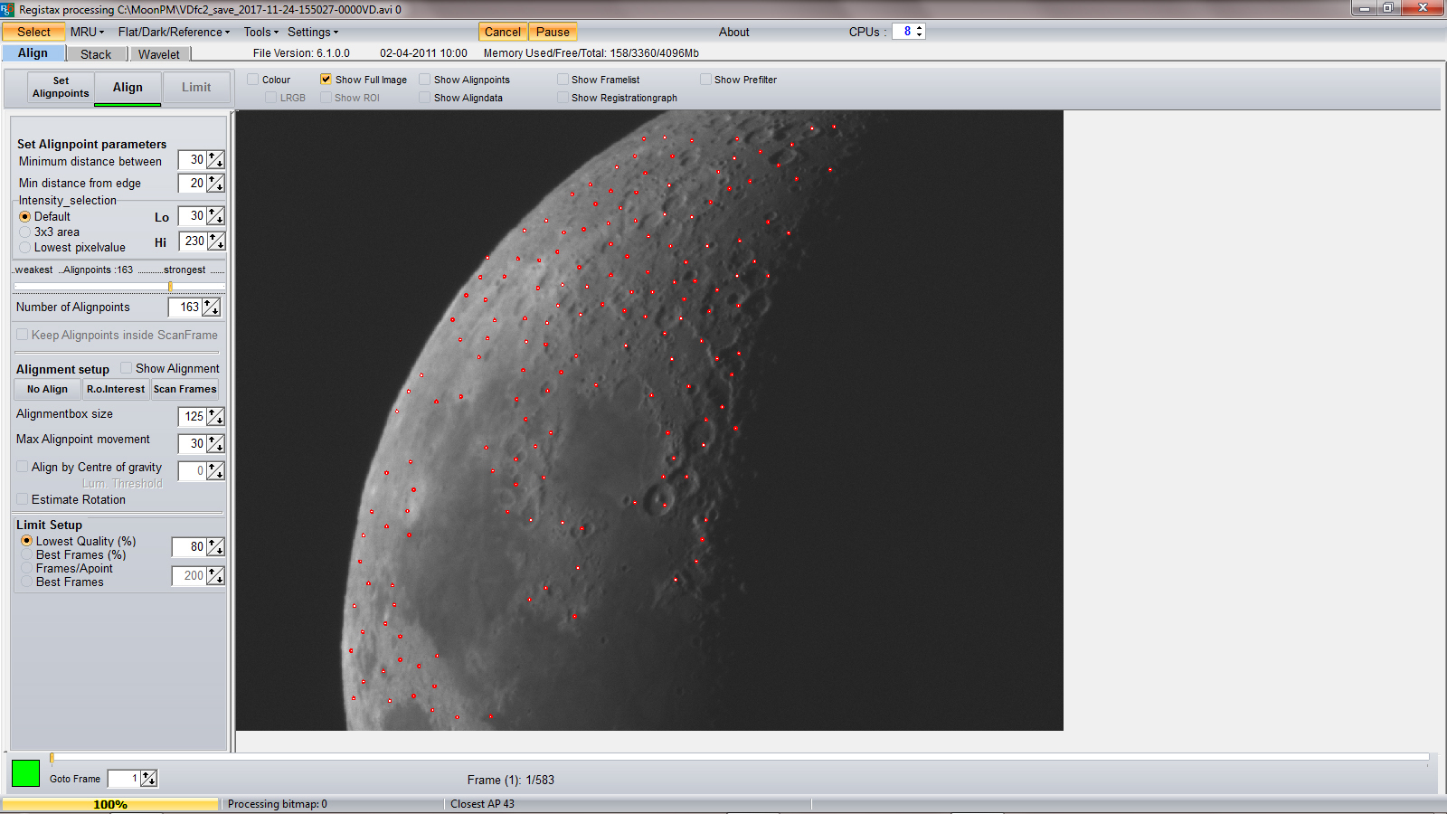
By adjusting the slider below the tab, the number of align points was reduced to a sensible number.
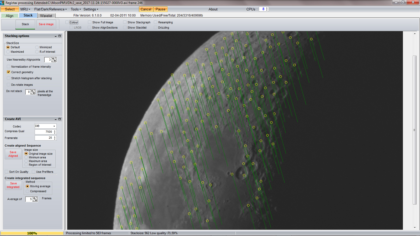
The ‘Align’ tab was then clicked upon and, after a short while, the following screen appears when the ‘Limit’ tab is clicked upon. The fact that the green lines are parallel indicates that the seeing was very good. Their length shows the movement across the sensor during the sequence capture. (I do like to allow some motion across the sensor to average out the pixel sensitivities.)
At this point the ‘Show Stackgraph’ box is ticked. As shown below, the top graph shows the image quality of each frame in rank order. Moving the slider below the graph to the left the lesser quality frames were removed from the number to be stacked. The lower graph shows the movement of each frame away from the reference frame. The slider on its left was moved down to remove those where the movement was greatest.
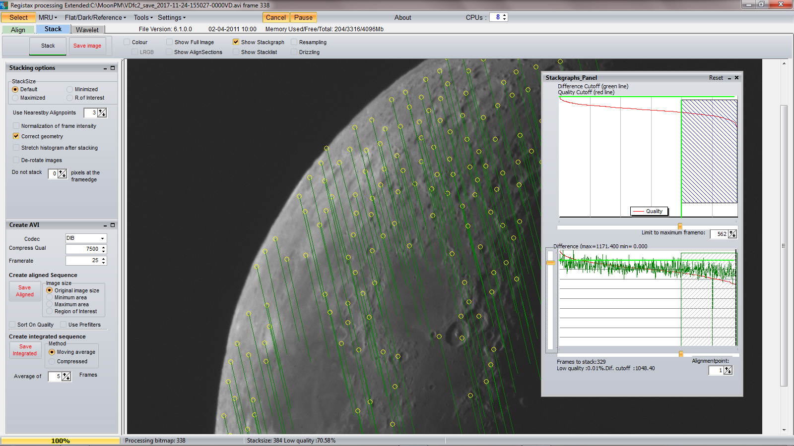
This left 329 frames which were to be stacked when the ‘Stack’ tab was clicked upon to give the result below. This is an average of all the frames. It is very smooth but not very sharp.
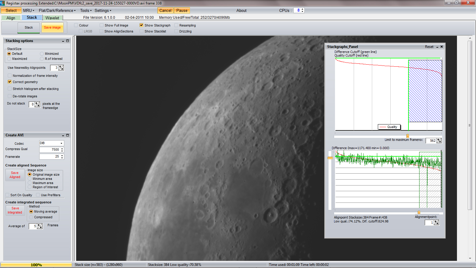
The result was saved as a 16 bit Tiff image – called a ‘pane’ when lunar imaging. This image holds great scope for sharpening and the usual method is to use the wonderful wavelets tool in Registax. However, there is an alternative called ‘Deconvolution Sharpening’ which aims, in an iterative way, to estimate how the image would have appeared if it had not been blurred by (in this case) the atmospheric turbulence. It does take some processing power so a reasonably fast processor is required. I have purchased the ‘Astra Image’ software package (https://www.phasespace.com.au/) which currently costs $42 dollars. Apart from deconvolution sharpening it has many other features for use in image processing. I was using an earlier version than is currently available with fewer deconvolution algorithms available though I now see that I can update it for free.
The Tiff image was loaded in Astra Image and, in the ‘Enhance’ pull down menu, ‘Devolution for Sharpening’ was selected. The latest version of the program gives quite a number of options. My earlier version has only 2 and I chose the Van Cittert algorithm to make 107 iterations with a blur kernel size of 1.59 and a devolution strength of 1. A part area of the image is shown which can be ‘trial’ processed so that one can quickly find how the resulting image will appear.
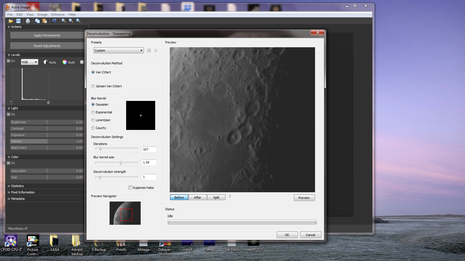
One can flip between the before and after deconvolution images which I have shown together in the composite image below.
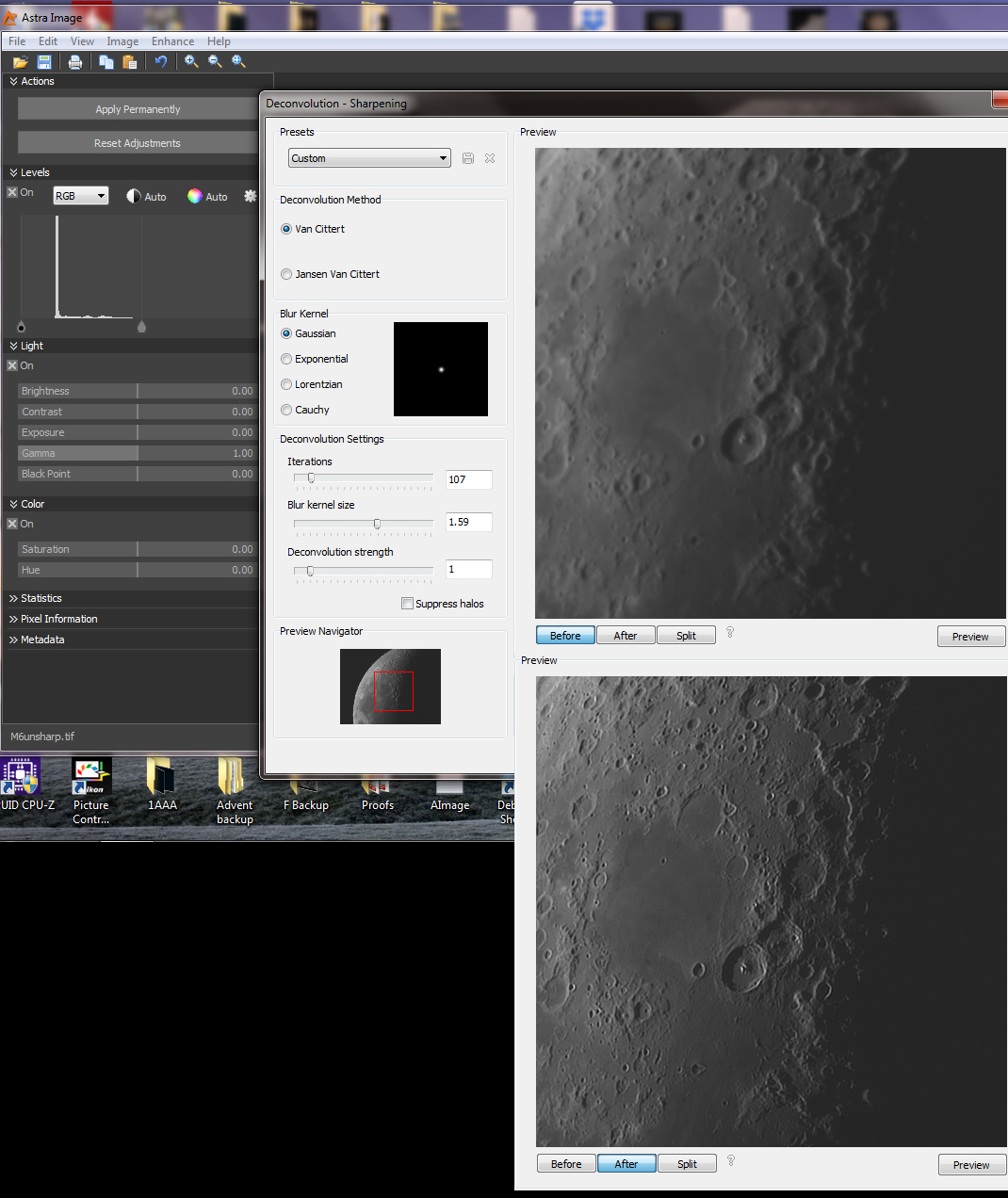
When I was happy with the result, the ‘OK’ tab was clicked upon to produce the sharpened image was saved as is shown below.
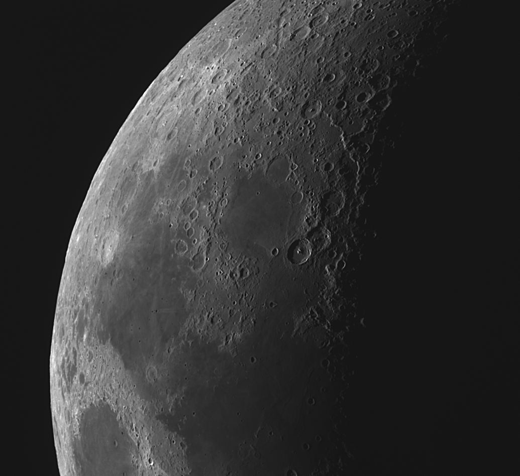
The three further panes were processed identically.
Microsoft ICE (Image Composite Editor)
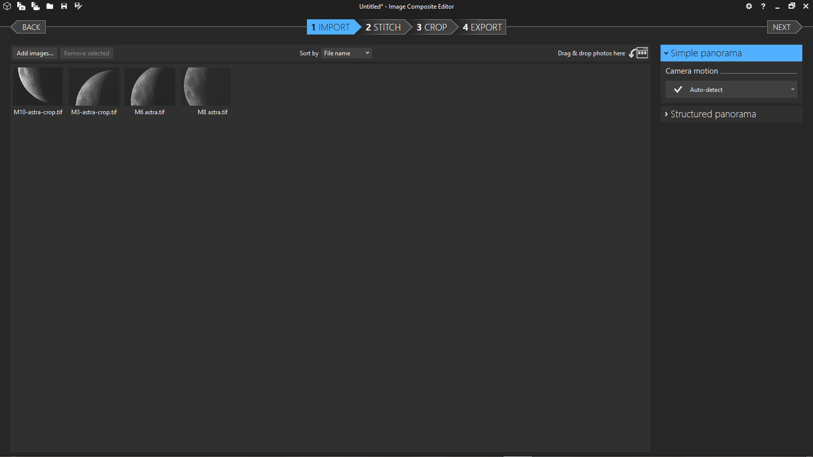
The (free) program was opened and the four panes imported into it.
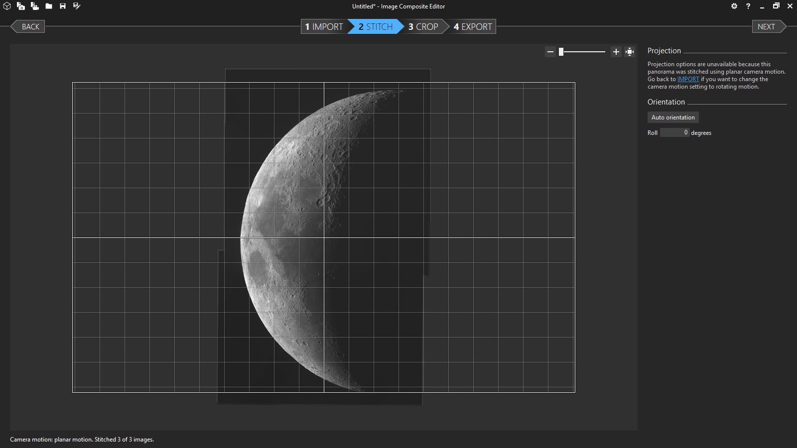
The ‘Stitch’ tab was clicked upon to give the result below.
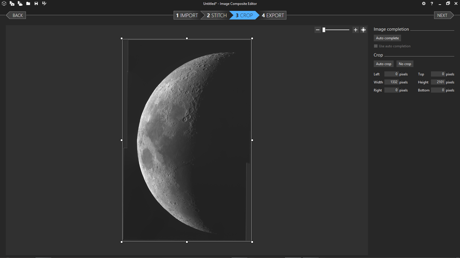
The crop tab was clicked upon to give a cropped result shown below.
The export tab was clicked and a Tiff image was exported.
Processing in Photoshop
The composite image was imported into Adobe Photoshop
The image was then cropped a little better, the canvas size increased somewhat and the image rotated both vertically and horizontally. I then used the levels tool to increase the overall contrast by bringing up the black level slider up to the edge of the histogram – so setting the black point of the image.
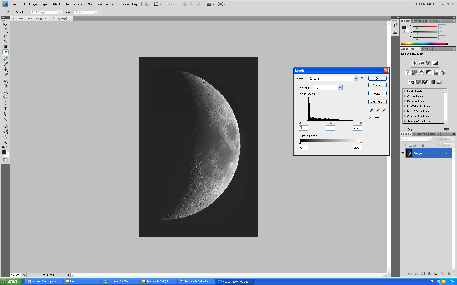
Some local contrast enhancement was then employed by using the ‘Unsharp Mask’ filter with a large radius and relatively small amount, adjusting both to find the best result. [This is the opposite to using the filter for sharpening when a small radius and large amount is used though there are far better sharpening methods in Photoshop.]
The final result is shown below.
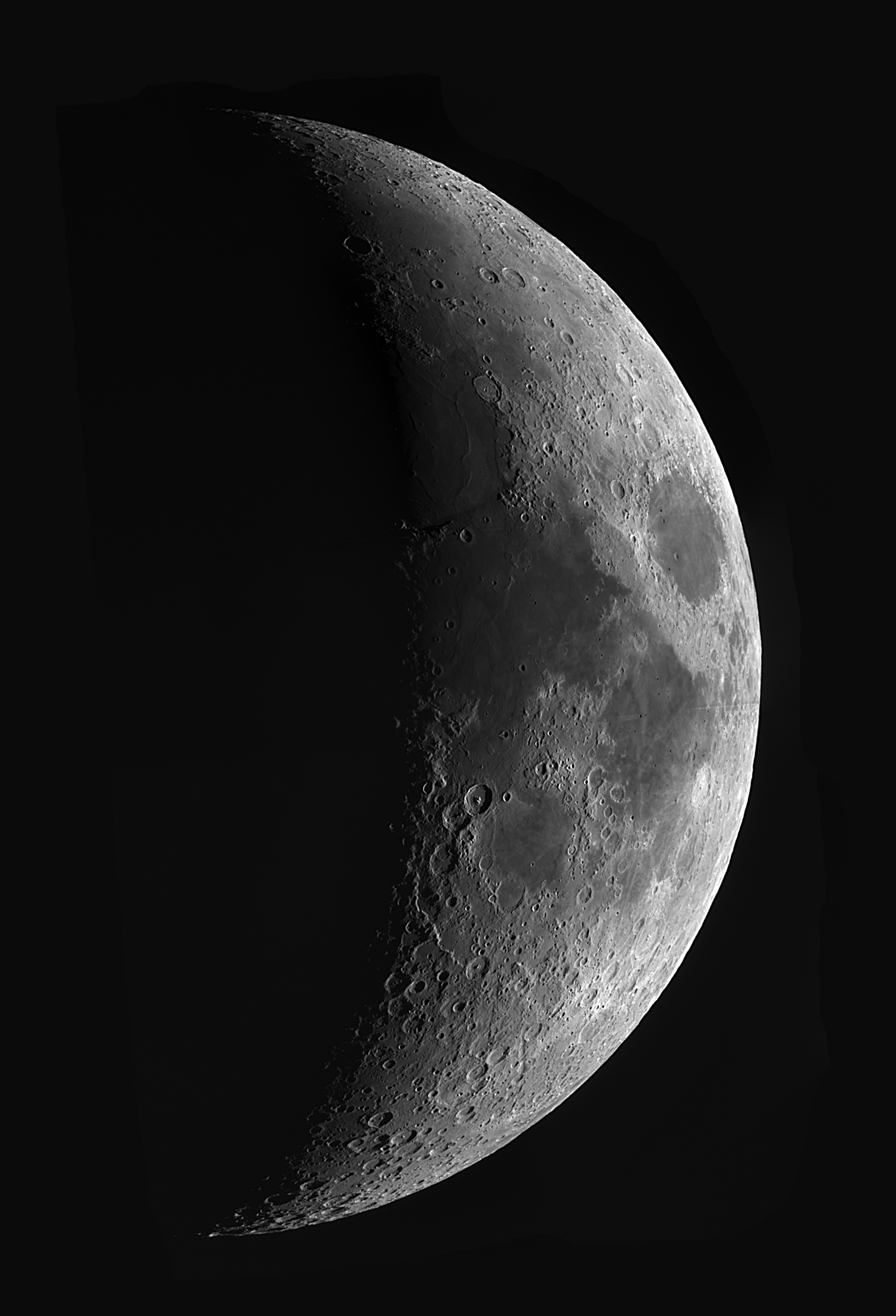
At the time of the imaging the Moon had an angular diameter of 29.9 arc seconds. There were a total 1,923 pixels across the lunar surface so each pixel corresponded to an angular size of 0.93 arc seconds. The 104 mm refractor has a nominal resolution of 1.1 arc seconds so that the sensor was undersampling the image and one might well achieve a higher resolution image by using a x2 Barlow lens prior to the camera so each pixel would correspond to an angular size of 0.43 arc seconds so satisfying the Nyquist sampling theorem. Whether this would produce a higher resolution image would depend on how steady the atmosphere was.
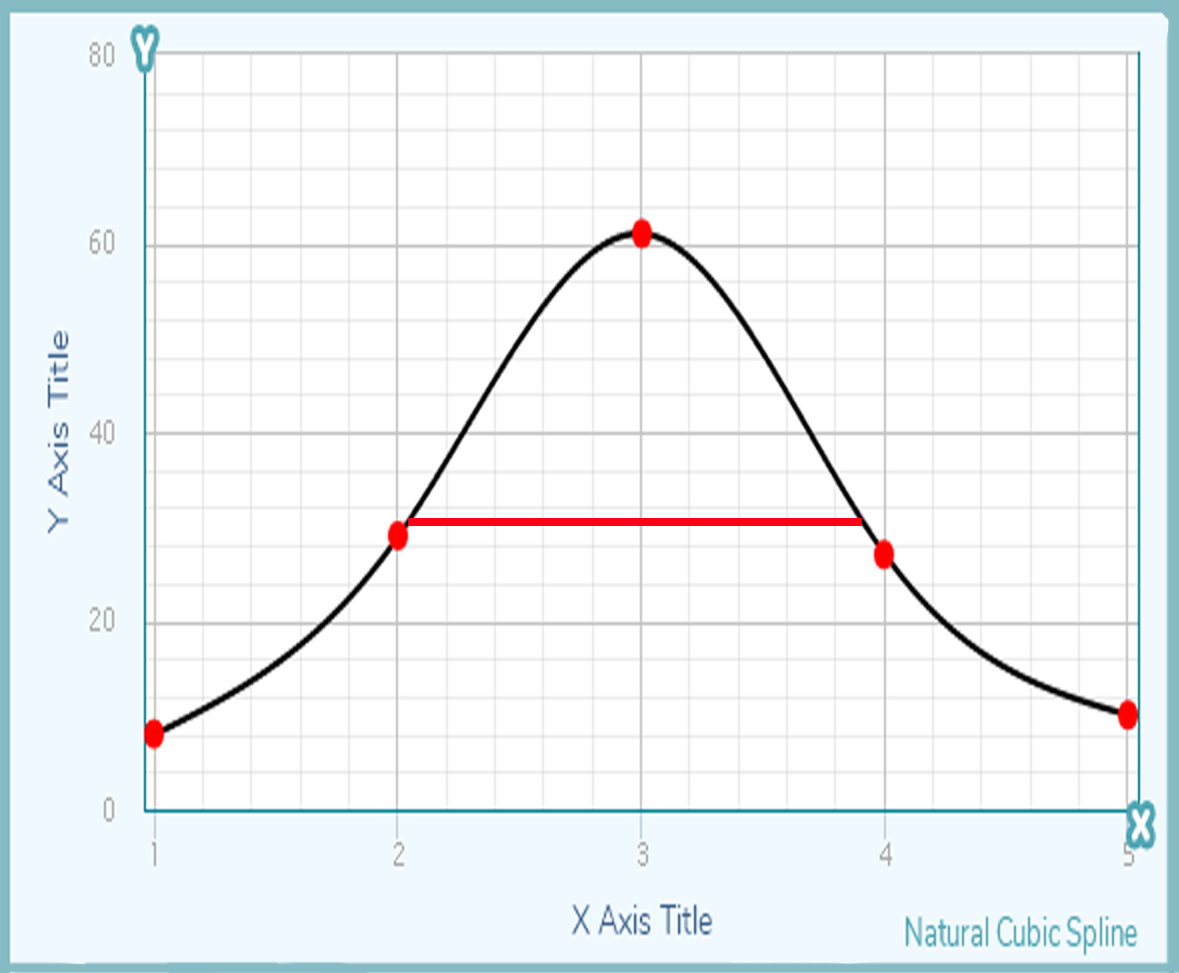
The image below is the pattern of pixels corresponding to (I suspect) a single bright point on the lunar surface.
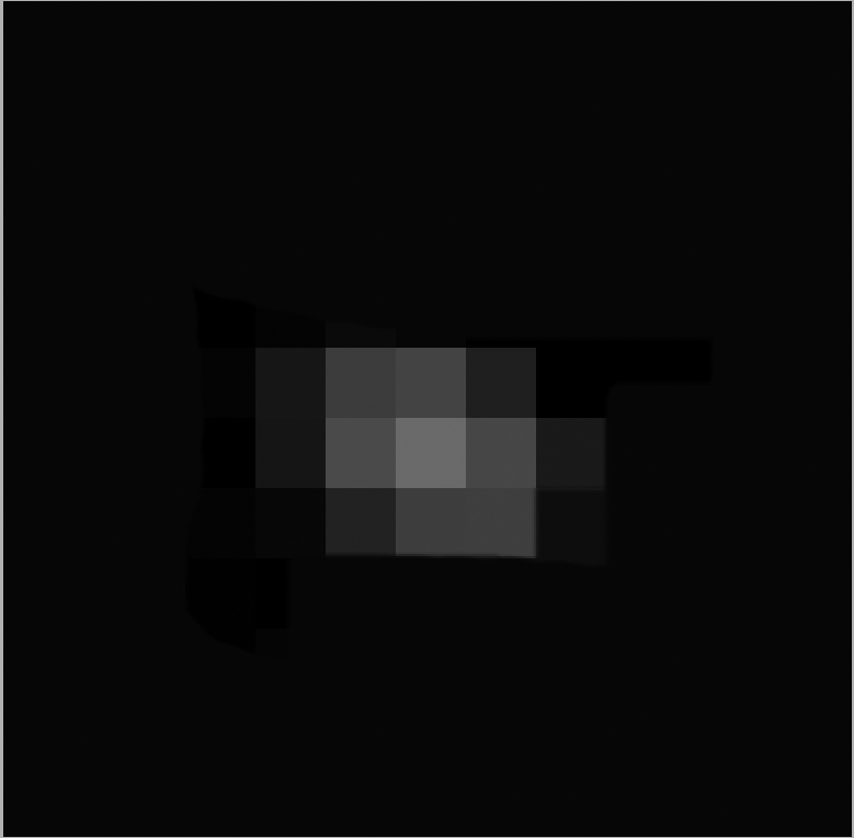
The brightness values across the pixels from left to right are: 8, 29, 61, 27 and 10. I have used MyCurveFit to make a best fit plot. The full width half maximum is ~1.8 arc seconds which I suspect agrees very well with what might have been expected.
