JULY 2023
Astrophotography using an Alt/Az mount
This article shows how, using a manual frame rotator and the provided BBC Basic program which can be run on Windows, Mac or Linux, one can manually rotate the camera to maximise the fully exposed image area when capturing a long total exposure.
At home, I can use a permanently mounted equatorial mount for astroimaging but this is not portable. I do, however, have an excellent iOptron AZ Mount Pro Alt/Az mount to take to star parties and dark sky sites and, at the latter, use this to carry out some astrophotography. It is sometimes said that one cannot do astrophotography using an Alt/Az mount but this is not true providing action is taken to remove the effects of frame rotation.
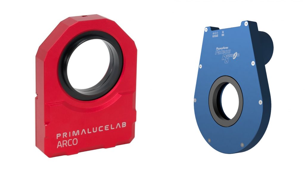
Many of the world’s largest telescopes are Alt/Az. Their cameras are mounted on computer controlled rotating platforms which keep the sensor aligned on the object. At the 2022 NEAF exhibition, ZWO announced that, in preparation, was a camera rotator which will be controlled by, I assume, the ASI Air. PrimaLuceLab provide their Arco rotator and Pegasus their Falcon rotator (£565) both of which can be controlled by a laptop. These will continuously rotate the sensor so long exposures could be made if the telescope was autoguided. In the manual method outlined below, the exposures will need to be short (but the mount can be unguided).
It should be pointed out that Alt/Az mounts cannot track near the zenith but, on the other hand, do not suffer from meridian flips as do many equatorial mounts. A useful feature when imaging with an Alt/Az mount is that the frames are automatically ‘dithered’ as the image (apart from the very centre*) moves across the sensor so eliminating what is called ‘Colour Mottling’ due to the varying sensitivity of the pixels over distances of 20 pixels or so.
[ *If the mount is tracking perfectly, then the central region will not be significantly dithered, so its actually better if there is a little movement of the image over the sensor during the total imaging period – this is very likely to be the case unless the mount is autoguided. ]
Planetary and Lunar imaging are not really affected as usually very short exposures or a video sequence is taken over a short time period. It is when one might want to image a deep sky object for an hour or two that problems will arise due to what is called frame rotation. To illustrate frame rotation one can consider the Orion constellation from rising in the east to setting in the west. In the east, Orion is ‘lying’ on its back, due south, it is vertical and, in the west, lying on its front. Its image will thus be rotate over the sensor of a camera mounted on an Alt/Az mount.

Provided that a lens that shows no or little distortion (rectilinear) or a telescope is used, a stacking program such a deep sky stacker or, my favourite, ASTAP will de-rotate the captured frames before stacking them and soan image can be made. [Many short focal length lenses will exhibit some distortion and, when many rotated frames are stacked, the outer parts become blurred.]
Exposure time
The frames must themselves have a short exposure otherwise stars will give elongated curved images away from the frame centre. One can take some test images with a range of short exposures to test for star trailing (in this case short arcs). The maximum exposure time will depend on the sensor size. It is not really sensible to image above 60 degrees elevation as this requires very short exposures but, in this worst case, for the UK (or similar latitude) when due south, the maximum exposure time for a full frame sensor is about 15 seconds but longer for a Micro 4/3 sensor. For the UK I now tend to take no more than ~30 second exposures using any of my mounts. Stacking a large number of frames allows satellite or aircraft trails to be eliminated if a ‘Sigma-Kapper’ stacking mode is used.
As an example, suppose an ASI 1600, APS C sized sensor were to be used which has a pixel size of 3.8 microns The equation to give the number of pixels traversed at the extreme corners of the frame is (t is in seconds):
Pixels Traversed = 0.271 x cos (latitude) x cos (azimuth) x t / cos (altitude)
This gives 0.325 pixels per second for my example imaging due south. Assuming one can tolerate a blurring of 7 pixels in the extreme corners, then the maximum exposure is given by:
t = 7 / 0.325 = 21 seconds.
If a Micro 4/3 sensor is used:
Pixels Traversed = 0.219 x cos (latitude) x cos (azimuth) x t / cos (altitude)
t = 7 / 0.219 = 32 seconds.
If a Full Frame sensor is used:
Pixels Traversed = 0.43 x cos (latitude) x cos (azimuth) x t / cos (altitude)
t = 7 / 0.47 = 15 seconds
So, using my Altair Astro 294 cooled Micro 4/3 sensor camera I could use ~30 second exposures.
Depending on how much the image has had to be cropped one might find that a movement of 7 pixels in the corners is too much. In which case the exposure must be reduced by the factor 7 / (allowed pixel movement).
The Alt/Az exposure problem.
As the frames taken of an image will rotate with respect to the sky, only the central part of the stacked image will have the full exposure. Providing that the object to be imaged does not fill the frame, one can crop this region from the full frame. How much of a problem this is depends on the rate of frame rotation during the course of the imaging.