JANUARY 2017
Everything about Refractors Part II: why do they give the highest contrast images?
This is one of over 100 illustrated articles in the Author’s Astronomy Digest including two others about refractors.
In the previous essay, I mentioned that refractors have the highest contrast of any telescope type – which makes them well suited to observing the Moon and planets. In this essay I will try to explain why this is so.
Image contrast is perhaps one of the key properties of a telescope and a subject that is not too well understood, with erroneous statements often appearing in the astronomical press. The following two sections will, I hope, allow you to understand the various elements that come into play to determine what is termed the contrast of an astronomical image. The approach that I believe gives the best understanding of the subject splits the discussion into two parts: firstly that of the overall contrast of the image and secondly what I term the ‘micro-contrast’ of an image. I am not aware of any other author taking this approach but I honestly believe that this is by far the best way of considering this very important aspect of telescope design. We will see that on both counts refractors are theoretically the best telescope type.
The overall contrast of an image
So what is meant by the overall contrast of an image? In an ideal world, the light that is recorded by a CCD camera of a particular feature in an image would only have come from the light emitted or reflected by that feature alone. This will rarely be the case. The lunar image at the left of the figure is obviously of low contrast – the blacks are grey, not black. In this case, the reason was due to the fact that it was taken in twilight and so sky light was falling uniformly across the image. [By taking a sky image with the same exposure just to the left of the Moon and subtracting this from the lunar image (using the ‘Difference’ blending mode in Photoshop), removed much of this unwanted light and produced the image on the right which has much higher contrast – quite a good tip!] However, after dark, there may well be light pollution spreading light into the image and, even with no light pollution, there will still be some ‘air glow’ reducing the contrast a little.
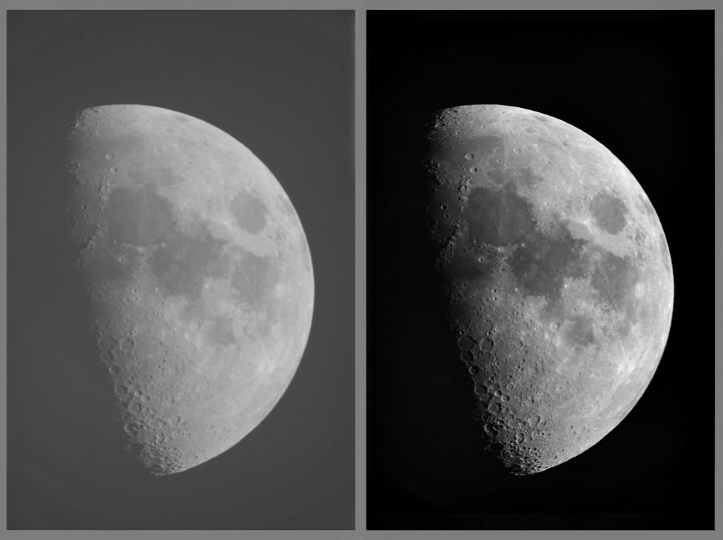
A low contrast (left) and high contrast (right) image of the Moon.
A major reason why refractors give images with higher overall contrast than reflectors is that objective lenses may only scatter ~2% of the light passing through them. If, as in the case of Fluorite doublets, one element is made of fluorite crystal – which essentially scatters no light – this is reduced to ~1% and a well baffled (see below) fluorite refractor can provide the highest overall contrast of any telescope. The use of my Takahashi FS102, f8, fluorite refractor enabled me to produce a very nice image of ‘Earthshine’ as the light from the illuminated part of the lunar disk did not ‘wash’ over the, far fainter, dark side of the Moon.
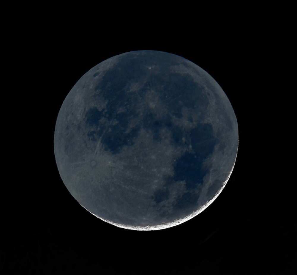
Earthshine
A second reason for reducing the overall contrast is when light scatters off the interior of the optical tube assembly. This is also why refractors can provide such high contrast images as a series of knife edge baffles reducing in size can be located within the optical tube to trap any scattered light. Matt-black flock coatings can also be used to reduce any scattering. My Cff Telescopes 127mm, f/7, refractor employs both as do other high quality telescope tube assemblies.
[An aside: many natural history photographers use highly expensive lenses when photographing wildlife. One of the very best lenses available for this use is the Canon EF 500mm f/4L IS II USM Lens costing over £6,000. It uses 16 elements in 12 groups incorporating both fluorite and ED glasses. Even with superb multi-coatings, these elements must scatter more light than a 2 element astronomical telescope so the overall contrast must be less. An 80mm, f/6 (so 480mm focal length), semi-apo refractor costing around £600 perhaps coupled to a field flattener (~£200) giving 4 elements overall should be able to provide equally good, if not better, images. The noise performance of the latest DSLR’s can usually cope with the reduction from f/4 to f/6. Ok, the focus is manual and so it would not be suitable for some applications but it can work and such systems are being used by wildlife photographers particularly if, say, photographing a nest so the focus will not change. I am not a wildlife photographer, but I used an 80 mm ED refractor (without field flattener) and Nikon D7000 APSC camera to capture this image of a mute swan which I took at my very first attempt at what is called ‘Astroscoping’ (as opposed to digiscoping) and which has graced the front cover of a magazine.]

Mute Swan
The micro contrast of a refractor’s image
As described above, the overall contrast of a refractor will be reduced by scattered light either from parts of the optical tube assembly or within the objective lens. The micro contrast, on the other hand, is determined by the effects of light that is diffracted by parts of the optical tube assembly. In this case, light is only moved from its rightful place by angular distances measured in arc seconds or arc minutes and is thus particularly important in the case of observing planetary disks where the angular scale of the observed object is similar in scale and the features on the surface may have low contrast as well.
In the case of a refractor the only diffraction effect is that caused by the fact that the telescope will have an aperture of a given size. The result is that a point source of light such as a star gives rise to a disc of light (whose size is determined by the aperture of the telescope) surrounded by concentric rings forming the Airy Pattern. If the aperture is unobstructed, as with a refractor, 84% of the light falls within the central disk and thus 16% lies in the rings − with the majority within the first ring whose diameter is about twice that of the central disk. Most, but not all, other telescope types will have a central obstruction, sometimes supported by a ‘spider’ which gives rise to additional diffraction effects so, again, a refractor can give the highest quality images.
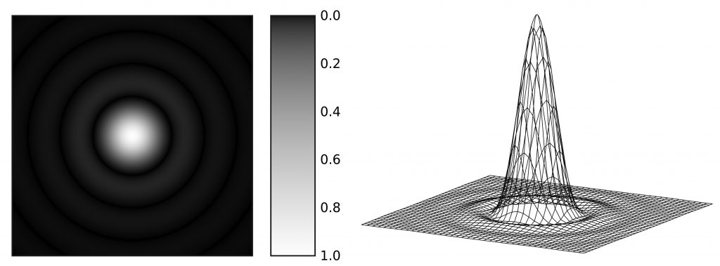
The Airy Pattern shown (left) as a greyscale pattern and (right) as a 3D plot. (Wikimedia Commons)
The resolution of a telescope
The detail in an image viewed by a telescope is theoretically limited by its resolution which increases with telescope aperture. This is usually limited by the atmosphere though the nominal resolution can be approached under excellent seeing conditions and with the use of ‘lucky imaging’ − selecting and stacking the sharpest frames from a video sequence. The resolution of a given aperture scope can be measured experimentally by, for example, observing when the two stars of a close double can just be split. This approach gave rise to the empirical ‘Dawes Limit’ as proposed by W.R. Dawes and gives the resolution, in arc seconds, as R = 4.56/D where D is in inches or R = 116/D where D is in mm. For a 100mm aperture scope this gives 1.16 arc seconds.
The Rayleigh Criterion states that a telescope can resolve two stars when the peak of one stars diffraction pattern falls into the first minima of the other. This gives somewhat lower resolution limit than that defined by Dawes, as in the Raleigh Criterion there is a drop of ~26% in brightness between the two peaks whereas in the case of the Dawes Limit the drop is only 5%. The angular separation between the centre of the Airy Disc and the first minima of the Airy Pattern is given, in radians (1 radian = 57.3 degrees), by 1.22 l/D, where l is the wavelength of the light. (Both l and D must be in the same units.) Using the wavelength of green light of 5.5 x 10⁻⁷m, this gives a resolution, in arc seconds, of 138/D where D is measured in mm. Thus, with a lens of aperture 100 mm, one gets a theoretical resolution of ~1.4 arc seconds.
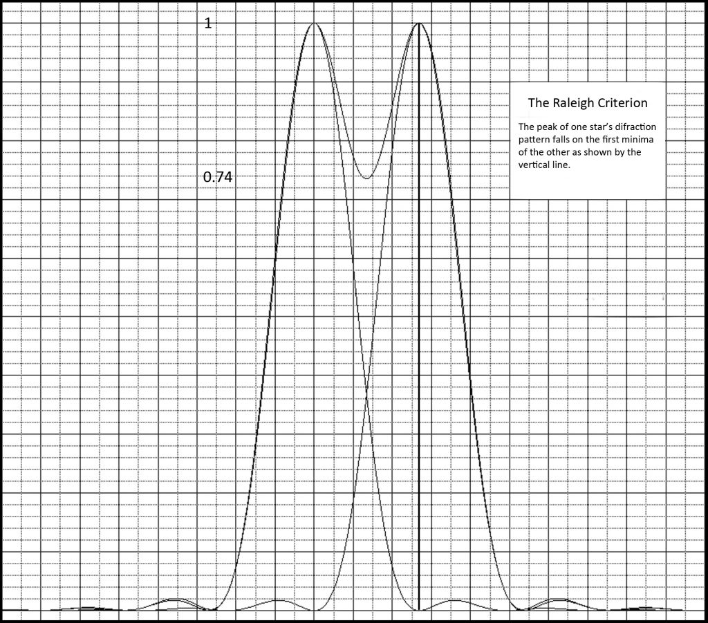 The Rayleigh Criterion.
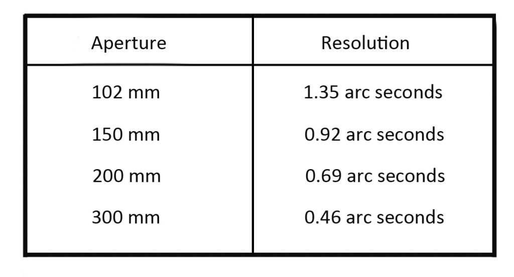
The theoretical resolution in green light for a number of telescope apertures.
Image quality
One factor in determining the image quality of a telescope is the precision with which the mirrors or lenses have been made. Refractors where the false colour (chromatic aberration) has been eliminated are often said to give exquisite ‘pin sharp’ images and there are several reasons why this might be so.
- A refractor is usually perfectly collimated − that is optically aligned − and tends never to need collimation whereas reflectors to tend to lose their collimation and need to be regularly collimated to give of their best.
- The central obstruction of a reflecting telescope will reduce the image quality somewhat compared to an identical aperture refractor.
- The overall contrast of refractors will tend to be higher.
- A refractor is likely to have an optical system of higher accuracy and so closer to optical perfection. The reason is very simple. It is actually four times easier to make a lens with a given optical precision than a mirror. Suppose a mirror had a ‘perfect’ surface except for a small part which is 1/8th wavelength below its surroundings. As the light is reflected the error in the light path length will be double this and so be 1/4 wavelength. The error in the path length for any deviation from a perfect surface is doubled. Lets now consider the surface of a lens which has a depression of 1/8th wavelength. Had it been filled with glass, the difference in optical path length would have been increased by the fact that the glass has a refractive index of ~1.5 − but this is only by ~50% more than the path though air. So the actual path length error will only be 1/16th wavelength − one quarter that of the equivalent error in a mirror!
How is the quality of a lens assessed?
There are a number of ways by which a manufacturer of mirror or lenses may specify the quality of the optics.
Strehl Ratio
This is, perhaps, the most obvious and best defined way of defining optical quality and one which is now coming into more common use. As described above, a refractor, as it has an unobstructed aperture, would ideally place 84% of the light from a star (when observed under perfect seeing) into the central disk of the Airy pattern. If the objective were perfect it would then be said to have a Strehl ratio of 1. No objective is perfect although some of the very best reach Strehl ratios well above .95 under test conditions. Some manufacturers may be willing to quote minimum Strehl ratios for their objectives – a value such as .95 or .96 – but it is interesting to note that the very ‘high end’ manufacturers, whose lenses often equal or exceed a .98 Strehl ratio, may not do so for fear of competition among their purchasers. The quoted Strehl ratio is usually for green light and may fall off somewhat towards the extremes of the visible spectrum. (Less so if Fluorite is used as the ED element.) An important point to note is this: it is virtually always that the atmospheric seeing that will limit the image quality of a good telescope and a Strehl ration of .95 or above can essentially be regarded as perfect.
Root Mean Squared (RMS) surface accuracy
Mirrors can now be tested using interferometric methods and these yield another way of defining the surface accuracy. The RMS accuracy of a mirror provides a statistical measure of the departure of the surface from the ideal shape. The RMS value can be converted into the Strehl ratio of the mirror. The approximate formula is:
Strehl Ratio = 1 – (2 π × RMS)2
Putting in, say, 0.028 for the RMS value, multiplying by 2 π and squaring gives 0.032, resulting in a Strehl ratio of .97. It should be pointed out that the effective Strehl ratio for a newtonian or catadioptric reflector will be less due to the effects of the secondary obstruction.
Conclusion
I hope that this essay will have explained to you why refractors can be near perfect optical instruments and I use mine − ranging from 60 to 127mm in aperture − more than any of my other telescopes, but that does not mean that you shouldn’t have a Newtonian, Maksutov or Schmidt-Cassegrain telescope. Above ~120mm aperture refractors become very expensive, and to observe or image faint objects such as planetary nebula or galaxies, larger telescopes are required and I will cover these in later essays. The final ‘Refractor’ essay, to follow next month, will survey the range of refractors available and show how, with additional ‘field flattening’ elements they can made more suitable for astroimaging.