NOVEMBER 2020
Field Flatteners and Focal Reducers
[This is just one of many articles in the author’s Astronomy Digest.]
When a digital camera is used for imaging with a telescope aproblem known a ‘Field Curvature’ can arise whose effects will be greater asthe focal length of the telescope become less and the size of the image sensorlarger. Whereas camera lenses aredesigned to give a flat field so that all parts of the sensor will capture asharp image, standard telescopes are not. The image plane is actually the curved surface of a sphere whose centrein the case of a refractor is the ‘nodal point’ of the objective lens. As a result, in order to correctly focus theouter parts of a flat sensor, it will need to be slightly closer to the lens ormirror. The shorter the focal length ofthe telescope the greater the problem as the curvature will be greater.
With telescopes of focal ratios greater than ~f/7 andsensors up to APS-C in size the captured images may not be materially affectedbut, with lower focal ratio telescopes and a full frame sensor, stars in the cornersof the frame will be distorted. Telescopes that aim to provide a flat field are called ‘astrographs’ andwill very likely contain one or more additional elements such as in theTeleskop Service 66 mm Quad astrograph which uses a triplet objective coupledwith a singlet lens part way down the telescope tube to flatten the field. The Vixen VC200L and the Celestron ‘Edge HD’catadioptric telescopes employ additional lens elements mounted within the rearbaffle tube to, again, provide a flat field with ‘clean’ stellar images out tothe edge of the frame.
Field Flatteners and Reducer/Flatteners
Curvature of field and the effects of lens aberrations distortingthe stellar images towards the edge of the field can be compensated for by theuse of either ‘Field Flatteners’ or ‘Reducer/Flatteners’ (called reducers fromnow on). The former will leave thefocal length of the telescope essentially unchanged whilst the latter willreduce the effective focal length by 0.8x, 0.7x or 0.6x, as well as flatteningthe field – these will both widen the field of view and reduce the focal ratioso shorter total exposures will be required. Many manufacturers will provide these designed specifically for a giventelescope but there are some that will work with a range of focal lengthtelescopes. For example, the ‘TeleskopService 2 inch flattener’ will work with a very wide range of refractors withthe distance from the flattener to the sensor adjusted to suit the focal lengthof the telescope. The required distance varies from ~100 to 130 mmas the telescope focal length increases from 450 to 800 mm. It does work very well. The tableshows the required separation between the rear of the flattener and the camerasensor.
♦ focal length< 450 mm: 128 mm
♦ focal length450-490 mm: 123 mm
♦ focal length500-550 mm: 118 mm
♦ focal length560-590 mm: 116 mm
♦ focal length600-690 mm: 113 mm
♦ focal length700-800 mm: 111 mm
♦ focal lengthabove 800 mm: 108 mm
These distances are quite large compared to typical flatteners or reducers which have a separation from lens to sensor of ~56 mm. This may be one reason why its performance is so good as the greater the distance of the flattener to the sensor, the wider the field that can be corrected. There is, however, a consequent problem. The camera will be at some distance from the telescope focuser and so have a large turning moment (particularly if it is a DSLR or full frame mirrorless camera) and so with a normal short ‘Vixen’ dovetail bar it will not be possible to balance the telescope/camera about the mount’s declination axis. The purchase of a longer bar will solve this problem.
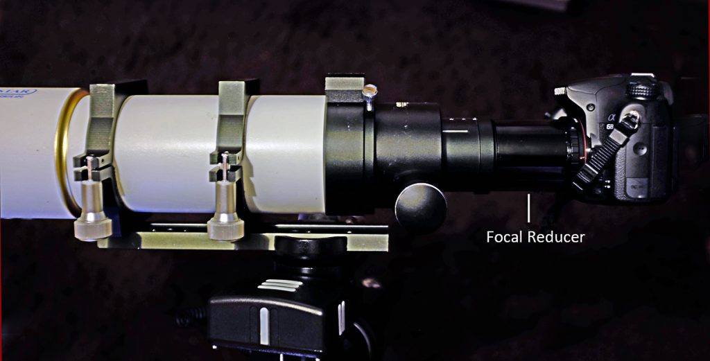
Another, low cost, example is the Altair Astro Lightwave 1.0x Field Flattener which can be used with f/5.5 to f/6.25 refractors and which requires the ‘standard’ ~56mm separation.
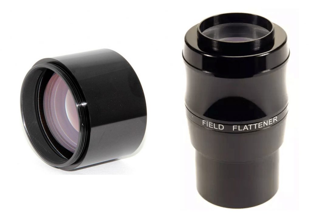
TheTeleskop Service 2 inch flattener (TS2F) in use
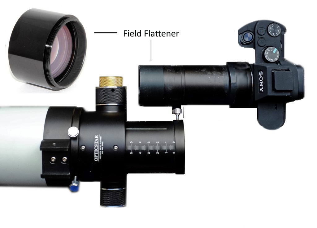
I have coupled the TS2F to an 80mm semi-apo refractor having a focal length of 500 mm. The flattener, barrel extender and Sony mirrorless T-mount bayonet are shown below. In use, the rear element of the flattener actually lies ~30 mm inside the focuser barrel rather than outside. One can from the figure seen below that this will locate the camera well to the rear of the focuser so an extended dovetail bar was used to mount the telescope/camera combination and retain balance about the Declination axis as shown in the image above.
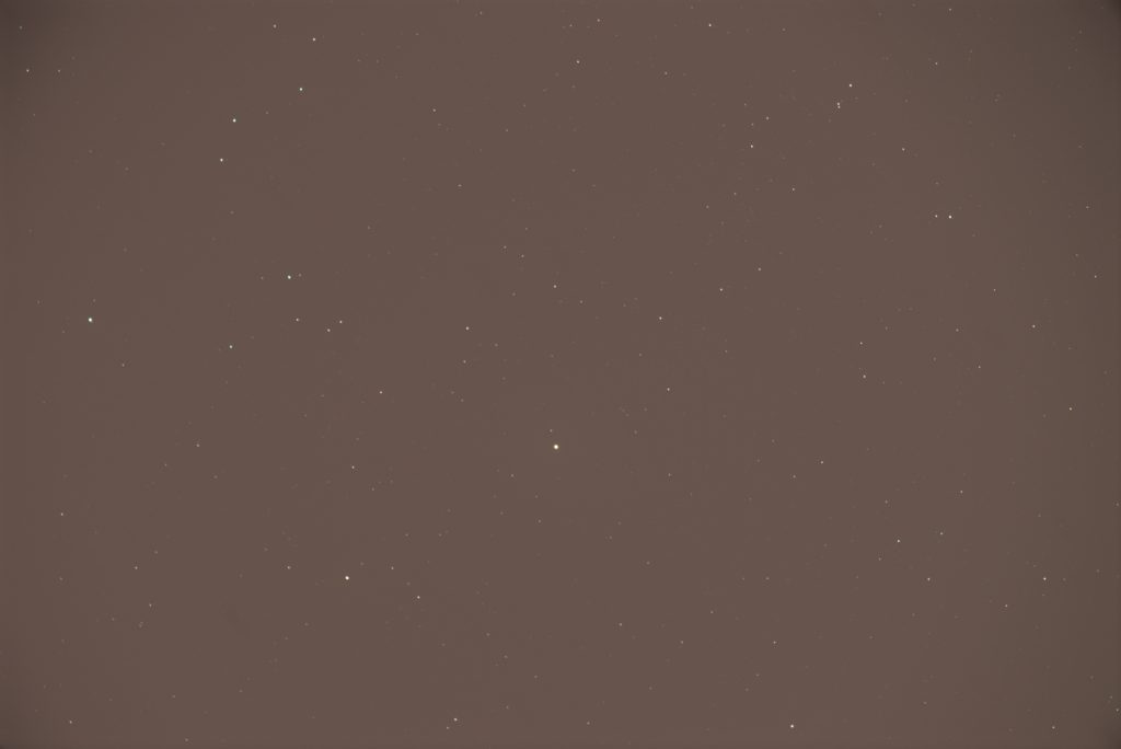
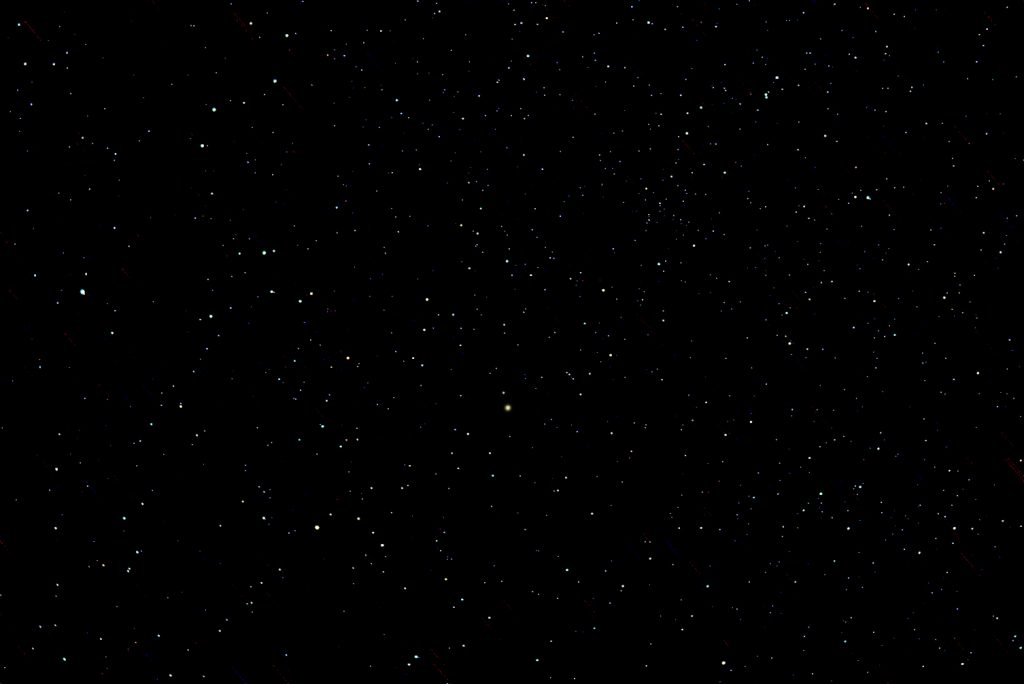
A test ‘star field’ image was taken of a region of sky centred on the Pole Star so that any miss-alignment of the mount would not cause star trailing. A set of 36 raw frames were taken with a full frame sensor Sony camera and aligned and stacked in Sequator (see article in the Digest). The sky was covered with a thin cloud layer producing some significant light pollution which for the purposes of this exercise was useful as it allowed the vignetting of the field to become easily apparent. The image below shows the output given by Sequator and the light pollution is very obvious.
If the ‘Dust and Scratches’ filter is applied in Adobe Photoshop or AffinityPhoto (see article in the Digest) to this image with a radius of ~20pixels, the filter ‘thinks’ the stars are dust and removes them so leaving anexcellent ‘flat frame’ which can actually be used to carry out a seconditeration of the align and stacking process and so remove the vignetting. The image below is of this flat frame and showsthe relatively minor vignetting that was present – which I found quiteimpressive and somewhat surprising.

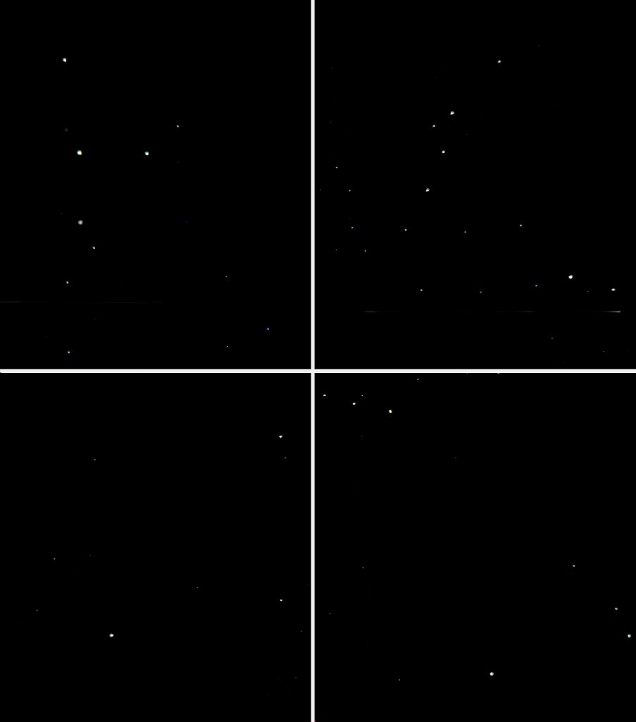
The light pollution was removed from the image as described in thearticle ‘Removing light Pollution …’ in the Digest and stretched to give thefinal image below. The star images inthe extreme corners of the image were not quite perfect but required just alittle effort to clean up giving an excellent result across the frame (see the techniqueused and a further example below).
The use of aReducer/Flattener
An example of a reducer is the TeleVue TRF 2008 which willwork well with refractors with focal lengths in the range 400 to 600 mmreducing the focal length by 0.8x. Coupled with my Takahashi 60 mm f/5.9, 354 mm focal length refractor (soless than the designed range) it produces an effective telescope focal lengthof 284 mm with a focal ration of f/4.7. Pleasingly, the field covers virtually all of a full frame sensor. [Takahashi do provide a dedicated fieldflattener for this refractor as well as a, somewhat expensive, 0.72x reducer.]
The figure below shows the heavily light polluted image thatwas the result of aligning and stacking28 raw frames in Sequator taken usinga full frame Sony camera.
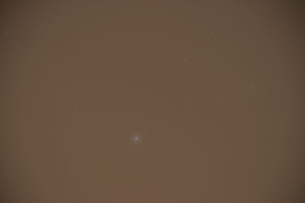
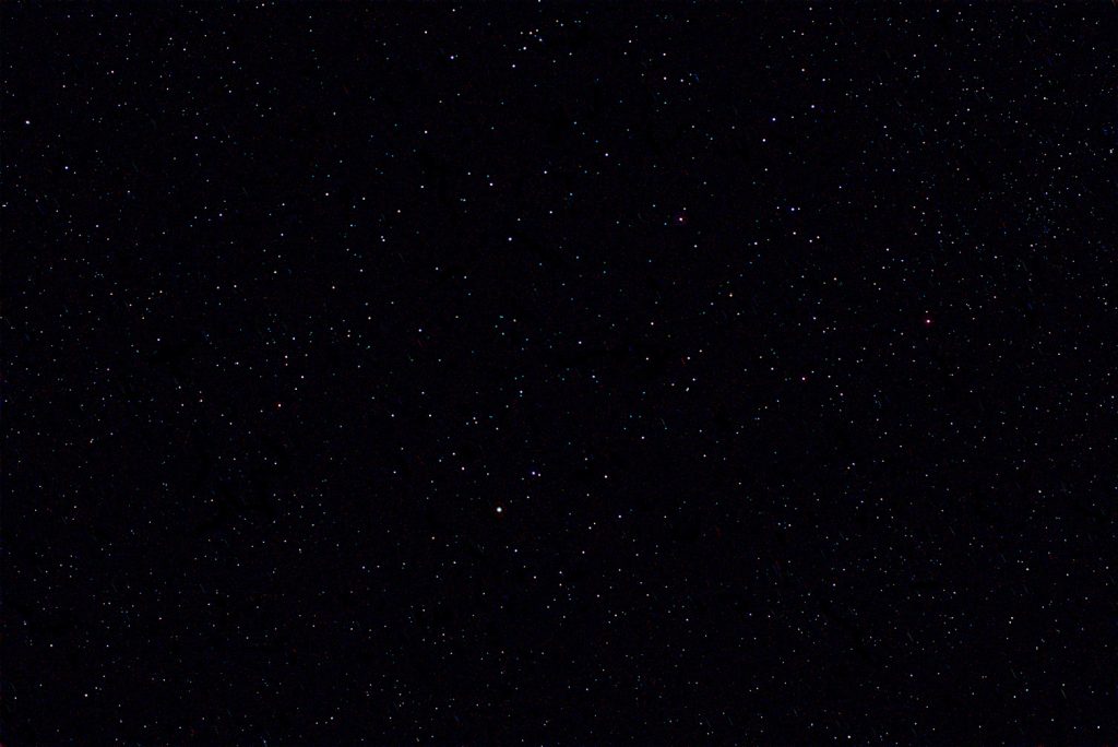
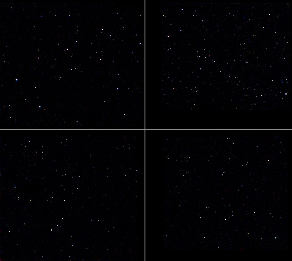
Again by using the ‘Dust and Scratches’ filter an image ofthe light pollution is produced which can also be used to re-process the framesand so eliminate the vignetting. Havingremoved the light pollution and stretched the image I was very surprised at theresult which showed that the stellar images remained acceptable well intothe corners of the frame as seen below in the full frame and ‘4 corners’images.
It is interesting to submit the captured star field to beplate solved by ‘Astrometry.net’ which returned the following solution.
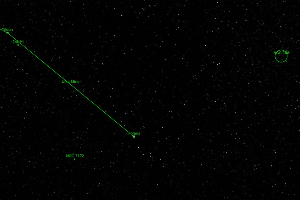
This defined the captured area as 7.3 x 4.88 degrees.
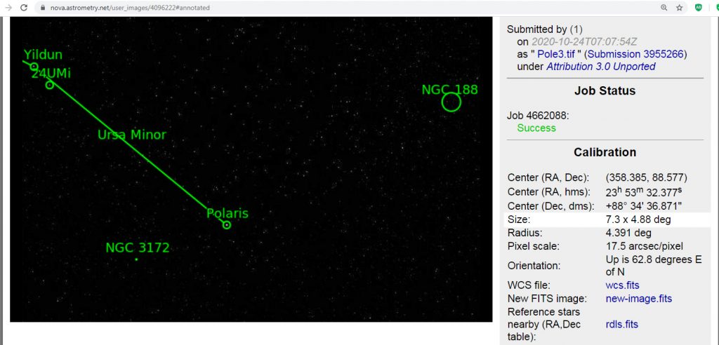
I compared this with the frames size given by the Blackwater Skies Field of View Calculator (see article in the digest) for the camera and telescope which gave a result of 7.14 x 4.76 degrees – so not exactly in agreement – whilst the Astronomy Now calculator gives 7.25 x 4.84 degrees – very close.
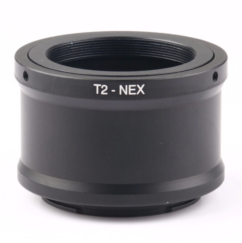
The reducers will usually screw directly into the bayonet part of a T-mount so, if used, the barrel part of the T-mount is not required and one may not need to use a focuser barrel extender to reach focus. Typically, they require a distance from the rear of the flattener to the sensor of ~56 mm. The thickness of the T-mount bayonet coupled with the camera flange to sensor distance will correctly achieve this when using a DSLR but, as the flange to sensor distance is less for a mirrorless camera, one needs to apply some extra separation. In the case of the Sony mirrorless cameras, Harrison Telescopes can supply a Sony e-Mount T2 adapter ring costing ~£15 which has additional length to provide the correct spacing.
Repairing Stellar Images
The Digest contains an article ‘Repairing Coma in Star Images’ to correct for ‘seagull’ or ‘comet’ type coma. However, if the coma is in the form of stars elongated radially away from the centre of the frame then there is a simple solution. The affected corner areas are individually selected and the layer duplicated. The blending mode is set to ‘darken’ and, with the move tool selected the mouse clicked on the upper (visible) layer – important. The arrow keys can then be used to shift the upper layer over the lower one and you will see how the distortion is removed before flattening the two layers. [This method will also correct for minor ‘star trailing’ when applied to the whole of an image.]
Return to Astronomy Digest home page