MARCH 2022
The Orion Constellation imaged using a fixed tripod
[This is just one of many articles in the author’s Astronomy Digest.]
This was an exercise relating to an astrophotography on-linecourse being given by the author where the students were asked to use a DSLRmounted on a fixed tripod to image a constellation.
As the camera is fixed in a particular direction, the starswill move across and rotate with respect to the sensor. This problem is worst at the CelestialEquator and becomes less so as one images towards the North CelestialPole. To avoid ‘star trailing’ exposuresmust therefore be kept short.
The simple rule for determining the maximum exposure lengthis to divide the effective focallength of the lens into 500. Todetermine the effective focal length one multiplies the focal length specifiedon the lens by the ‘crop factor’ of your sensor.
Full Frame 1
Canon APS-C 1.6
Nikon APS-C 1.5 (and all other APS-C)
Micro 4/3 2
So a 35 mm focal length on a Nikon APS-C camera is 52.5 mmand thus a maximum exposure is 10 seconds is suggested.
Exposures can be longer nearer the Celestial Pole so this exposure time can be divided by the Cosine of the declination [Cos(Dec)]. For example Cassiopeia is at +60 where Cos (60) is 0.5. So one can multiply the exposure time by 1/Cos(Dec) which in this case is 2 so that, with this lens and camera, one could then increase the exposure time to 20 seconds.
In fact with the latest high resolution sensors, 500 issomewhat on the high side and many are now using 300 instead. However, in the example that follows usingthe 500 rule, the star trails were very short and, as will be explained below,can be easily removed in post processing.
Equipment andexposures
The lens used was 50 year old, 50 mm, Helios Lens attachedto a Sony Full Frame camera so the effective focal length stays at 50 mm andthus 10 second exposures were employed. 115 frames at ISO 800 were taken saving both raw and Jpeg frames. [Even if raw frames are to be used forprocessing, it is far easier to inspect the Jpeg frames to spot problems – inthis case it became obvious that the final 15 frames were partially cloudcovered and so were deleted.]
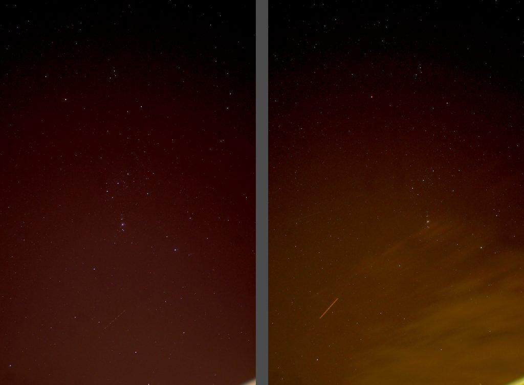
The image below is a comparison of the first and last Jpegframes (somewhat stretched) showing how the image has moved across the sensorduring the period of the exposures and also that light pollution was present – increasing, as expected,towards the horizon.

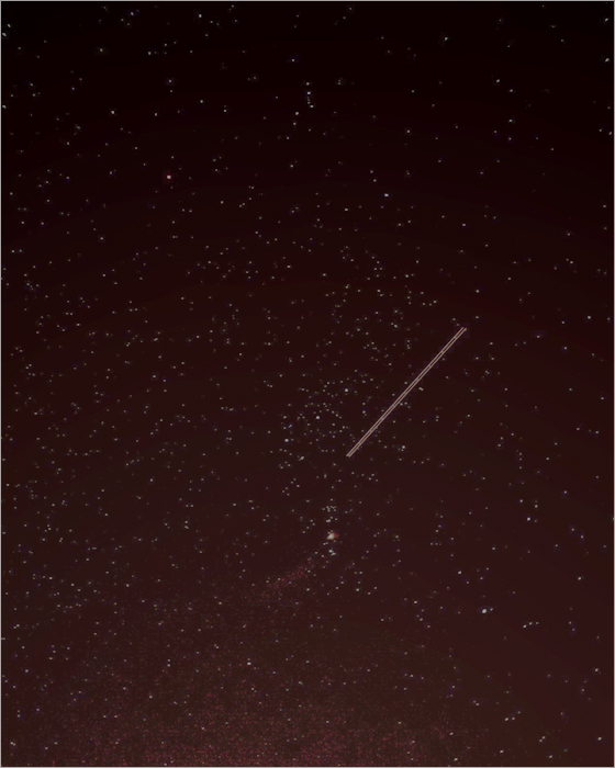
Plane trails could just be seen in both these frames withthe worst affected frame shown below. Happily, these can be removed in the image processing.
